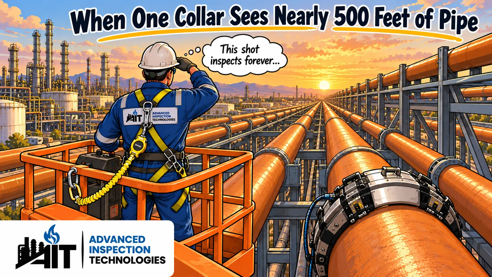
The 8-inch line sits up in a large pipe rack, coated, still in service. Conventional ultrasonic thickness (UT) could chase readings point by point — if you had the scaffolding, the time, and a reliable guess about where corrosion likes to hide. On a run like this, that guess is expensive.
So the crew clamped a guided-wave transducer ring around the pipe and shot both directions from a single collar.
What came back was the kind of display that makes Guided Wave Testing (GWT) — also called long-range ultrasonic testing (LRUT) or Guided Ultrasonics (GUL) — earn its keep: clean weld and support reflectors marching out from the ring, Distance Amplitude Correction (DAC) curves stepping down with range, and usable signal pushing past two hundred feet each way. On this coated 8-inch process line, one bi-directional test position covered roughly 473 linear feet from that single collar — range limited by elbows in one direction and by the last resolvable girth weld in the other.
That's the point of the method. Not a thickness number under the probe. A screen of the pipe wall volume for a long stretch of piping, from one access point.
What guided waves actually do
Unlike conventional UT bulk waves that interrogate the wall right under the probe, guided waves are constrained by the pipe's own geometry. A ring of transducers around the circumference launches a low-frequency wave (commonly in the tens of kilohertz) that travels axially along the wall — often using a torsional mode such as T(0,1) — in both directions from the test location.
In pulse-echo mode, the same ring listens for reflections. Time of flight places a feature relative to the collar. Amplitude, circumferential extent, and waveform behavior help separate routine geometry (girth welds, supports, tees, reducers, elbows) from changes that look more like wall loss.
That's why the A-scan on a good shot looks busy in a useful way: every weld returns a strong, full-circumference reflector; supports and branches show up as smaller, often incomplete responses; and anything that looks like localized metal loss has to be judged against that background — and against the DAC curves set for call and weld thresholds.
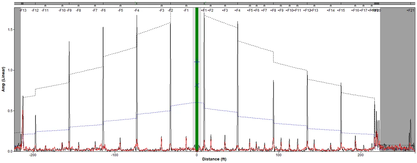
Long-shot bi-directional Guided Wave A-scan — client/site identifiers removed.
Where the method earns its keep
GWT is a screening tool. It is especially useful when:
- The line is elevated in a rack and access is limited
- Insulation, coating, or burial makes continuous conventional coverage impractical
- You need 100% wall coverage along a long run without guessing the hot spots in advance
- Integrity wants a fast map of where to spend follow-up UT or visual effort
On this recent AIT scope, two test positions on the same 8-inch circuit screened on the order of 500+ linear feet total. One position was the long shot — nearly 473 feet. The other was short by design: successive elbows in both directions clipped the range to about forty feet. That contrast matters. Guided waves don't invent access. Geometry still wins.
What the long shot is really showing
Look at a long bi-directional display carefully and you're not staring at "noise." You're looking at a map of the pipe's own language:
- Strong, regular peaks at girth welds
- Smaller responses at supports
- Bends and elbows that both reflect and eventually stop the useful range
- A dead zone and near-field region close to the ring where sensitivity is reduced (roughly the first couple of feet, depending on setup)
- Far-field attenuation that eventually swallows the signal — the grayed-out ends of the plot
On a clean coated line with solid signal-to-noise, weld reflectors can still be classified as welds rather than metal loss when amplitude, full circumferential extent, and field visual/UT at the collar support that call. That's field judgment — the part of GWT that software alone doesn't replace.
And the method still has hard limits. Successive elbows, flanges, large branches, and heavy attenuation (wet coatings, certain soils, bitumen, etc.) cut range. GWT does not hand you a precise minimum remaining wall the way a good UT reading or phased array scan can. When something looks relevant, the integrity answer is still: go prove it locally.
How AIT crews treat a GWT result
At Advanced Inspection Technologies (AIT), a guided-wave shot is never "done" when the A-scan looks pretty. The workflow is:
- Establish test positions that maximize coverage without pretending past geometry that will kill the wave
- Capture bi-directional data with documented procedures and acceptance criteria
- Classify features vs. indications — welds and supports are not automatically "hits"
- Verify baseline condition at the collar with visual and UT thickness
- Feed the integrity program: reinspect interval, follow-up locations, or a clean bill for that screened length
On the long shot described here, supplemental UT at the ring locations sat near nominal wall for 8-inch STD pipe, coating showed only light chalking at the test spots, and no relevant wall-loss indications were called across the screened length. The recommendation was the unglamorous one integrity programs actually need: keep it in the program and come back on a 3–5 year cadence unless risk factors change.
The takeaway
Guided Wave UT doesn't replace local thickness work. It decides where that work is worth doing — and proves when a long coated run in the rack is still speaking the language of welds and supports, not metal loss. When one collar can illuminate nearly five hundred feet of pipe with a clean bi-directional display, you're not saving a few probe placements. You're buying a defensible screen of piping that would otherwise stay invisible until someone guessed wrong.
If you're looking at elevated, coated, or otherwise hard-to-access process piping and wondering whether a guided-wave screen would shrink the UT footprint — or expand what your integrity program can actually see — AIT is happy to talk through what a real long shot looks like on your circuits.