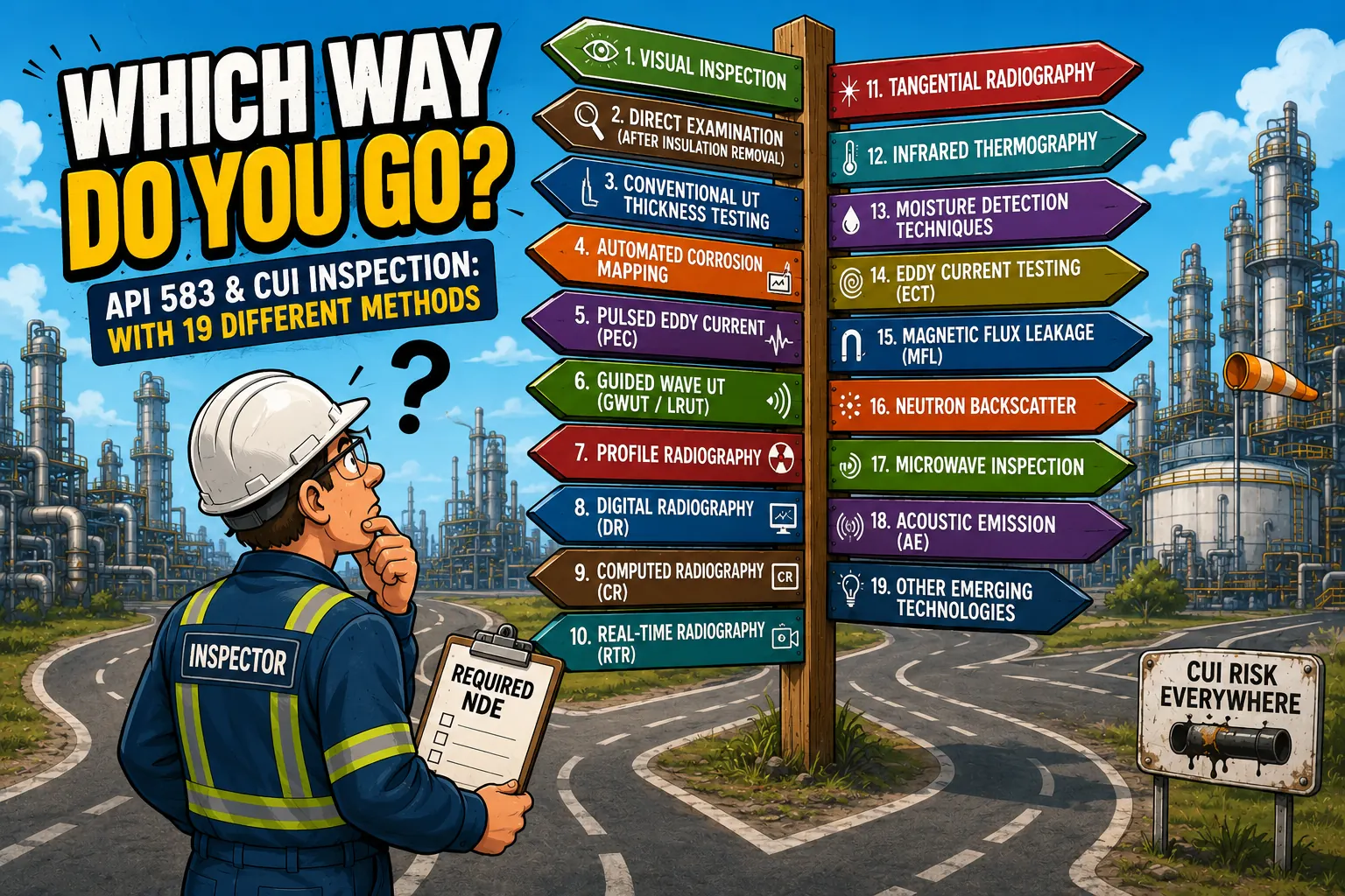
With 19 NDE methods discussed in API RP 583, knowing which technology fits your specific application is the real inspection challenge.
The 6-inch carbon steel line runs 30 feet up the north face of the crude unit, wrapped in mineral wool and jacketed in aluminum. It's been in service for eleven years. The operating temperature cycles between 180°F and 250°F — squarely in the CUI susceptibility window. Nobody has touched that insulation since the last turnaround, and nobody knows what's happening underneath it.
That scenario plays out in every refinery, chemical plant, and petrochemical facility in the country. Corrosion Under Insulation (CUI) is one of the most persistent, expensive, and dangerous damage mechanisms in the process industry. It hides. It progresses silently for years. And when it shows up — as a leak, a failed hydro, or a wall loss callout at the worst possible time — it's rarely a surprise to the corrosion engineer who's been watching the risk accumulate in the RBI database.
The inspection challenge is real: you have miles of insulated piping and vessels, limited access windows, operating pressure constraints, and a maintenance budget that doesn't stretch to stripping every line. What you need is a strategy — and API RP 583 lays out the framework. What it also does is present owner-operators with a substantial list of NDE technologies that can be applied to CUI programs.
Nineteen of them, depending on how you count. That's not a typo. The range of methods now available for CUI detection, screening, and sizing is genuinely broad. Each has strengths. Each has limitations. And the biggest mistake an inspection program can make is picking one method and assuming it covers everything.
There Is No 'Best' CUI Inspection Method
That's the uncomfortable truth at the center of every CUI program. An owner-user who asks 'what's the best technology for CUI?' is asking the wrong question — not because there's no answer, but because the right answer depends on four or five variables that are different for every line.
What technology do you pick for a buried crude line with 4 inches of calcium silicate insulation? Versus a 90°F cold-service ammonia line? Versus a 400°F process pipe with aluminum jacketing in a 60-foot pipe rack? Different problems. Different answers. Here's how the major technologies stack up.
The Method Landscape: What Each Technology Does
1. Visual Inspection
The oldest method and still the first line of defense. A trained inspector walking the line, looking for failed jacketing, missing caulk, water staining, rust bleed, or insulation banding failures — these are the leading indicators that CUI has a pathway. Visual inspection costs almost nothing and sets the priority list for everything that follows. Its limitation is obvious: it sees the outside of the jacket, not what's beneath it.
2. Direct Examination After Insulation Removal
Not glamorous, but definitive. Strip the insulation, clean the surface, run conventional UT or a straight-beam corrosion scan. You get the clearest picture possible of actual wall loss, pitting depth, and surface condition. The problem is cost, schedule, and scope: at scale, stripping every suspect section is neither practical nor budget-feasible. The goal of most screening technologies is to identify where this step is actually warranted.
3. Conventional Ultrasonic Thickness Testing (UT)
The workhorse of thickness measurement. A single transducer, a calibration block, and a trained technician can confirm remaining wall at a specific point with high accuracy. Fast, portable, cost-effective. The limitation: it's a point measurement. If you're not scanning over the worst spot, you miss it. On a run of insulated pipe, this is a confirmation tool, not a screening tool.
4. AUT — Automated Ultrasonic Testing (Corrosion Mapping)
AUT uses encoded ultrasonic scanning — either with a manual encoded scanner or a fully automated scanning frame — to build a C-scan image of wall thickness across a defined area. The result is a color-coded map showing thickness variation across the pipe OD, exposing localized pitting and general wall loss that spot UT would walk right past. Every data point is position-encoded, producing an auditable record that feeds directly into fitness-for-service assessments and remaining life calculations. The limitation is access: insulation must be removed over the area being scanned, and surface preparation is required for reliable probe coupling. This is not a through-insulation method — AUT is a characterization and sizing tool deployed after screening methods have identified priority areas, most commonly during turnarounds when access is available.
5. Pulsed Eddy Current (PEC)
PEC sends a pulsed electromagnetic field through insulation and fireproofing and measures the time-decay of the eddy currents induced in the pipe wall. It reads average wall thickness over a footprint — typically a 3-to-6-inch area — without requiring insulation removal. Aluminum jacketing, mineral wool, calcium silicate, cellular glass, even up to 150mm of fireproofing: PEC works through all of it.
Where PEC earns its keep is systematic screening of insulated piping and vessels at operating temperature. The probe clamps or holds against the jacket. You record, you flag anomalies, you move down the line. A single crew can cover significant footage in a shift — far more than insulation stripping could ever achieve.
The call in the field is whether a low-reading indication represents real metal loss or probe coupling artifact. That judgment separates useful screening data from noise, and it's where inspector experience matters most. PEC is a screening tool — it feeds UT follow-up, not fitness-for-service calculations directly. Wall thickness resolution is lower than conventional UT, and the method doesn't perform well on non-ferrous alloys. For stainless steel lines where External Chloride Stress Corrosion Cracking (ECSCC) is the concern, a different approach is needed.
6. Guided Wave Ultrasonics (GWUT / LRUT)
A collar of transducer elements wraps around the pipe at one location. Long-range guided waves propagate down the pipe in both directions — screening 50 to 100 feet from a single test point. Reflections from wall loss features return to the collar and appear as signals above the baseline noise floor.
Guided wave covers distance. For insulated pipe racks, road crossings, pipe bridges, or lines where access is restricted, a few collar placements can screen a run that would otherwise require scaffolding at every inspection point. It's particularly effective for finding discrete CUI attack zones — localized pitting or general thinning — in long, otherwise inaccessible runs. Limitations include sensitivity to gradual distributed metal loss, complex geometries like elbows and tees, and liquid-filled lines that significantly limit range.
7–9. Profile Radiography / Digital Radiography (DR) / Computed Radiography (CR)
These three methods share the same fundamental technique: a radiographic source is placed on one side of the insulated pipe and a detector on the other. The pipe wall profiles against the beam, and changes in wall thickness — particularly at the pipe's tangential edges — appear as variations in the resulting image. What separates them is the recording medium. Conventional profile radiography uses film. Digital Radiography (DR) replaces film with a flat-panel digital detector array, delivering immediate image review in the field. Computed Radiography (CR) uses a phosphor imaging plate that's processed separately, offering filmless results with equipment geometry similar to conventional film RT.
The physics, the source geometry, the interpretation workflow, and the fundamental limitations are the same across all three. All require access on both sides of the pipe, radiation exclusion zones, and licensed radiographers. All are most effective on smaller-diameter piping — typically under 10 to 12 inches — where the tangential profile geometry produces useful density contrast. For carbon steel lines with insulation in place, this remains one of the most reliable methods for profiling wall loss without stripping. DR and CR offer the practical advantages of digital image storage, faster review cycles, and integration with inspection data management systems.
10. Real-Time Radiography (RTR)
RTR is a fundamentally different animal. Where profile radiography produces a static density image for quantitative interpretation, RTR uses a low-energy X-ray source in a C-arm or handheld configuration that wraps around the pipe OD. The inspector moves the device along the pipe surface while watching a live video feed of what's happening beneath the insulation — in real time.
The best-known system for CUI applications is the OpenVision platform (DX and HD) from QSA Global. The OpenVision HD uses a 70 kV X-ray source with a highly collimated beam and internal shielding that limits the radiation footprint to roughly one meter — allowing daytime screening in many facilities without the large exclusion zones required by conventional RT. Radiographers can cover hundreds of feet per shift at approximately 30 seconds per foot, visually identifying CUI indicators such as external pitting, scale buildup, wall loss, and wet insulation on pipe diameters up to 36 inches, through mineral wool, calcium silicate, and metal jacketing combinations.
The critical distinction: RTR is a qualitative screening tool. The inspector is watching for visual indicators — blistering, corrosion product, surface irregularity — not producing a calibrated thickness measurement. Where RTR flags an anomaly, profile radiography (DR or CR) or conventional UT follows to confirm and quantify. Used correctly, RTR is one of the fastest CUI screening technologies available for accessible, above-grade piping.
11. Tangential Radiography
Tangential radiography appears in API RP 583 — specifically in a table discussing application limits for tangential and film density radiography — but it is treated as a sub-technique within the profile radiography family rather than a fully standalone method. The tangential technique directs the beam along the tangent of the pipe wall to maximize contrast at the pipe surface, and is particularly useful for sizing shallow external corrosion and profiling wall loss depth more precisely than standard profile geometry allows. In practice, it's an extension of the same profile RT workflow, applied when tighter sizing data is needed to support a fitness-for-service assessment.
12. Infrared Thermography (IRT)
Active thermography — heating the surface or exploiting temperature differentials — can reveal moisture intrusion beneath insulation, compromised jacketing, and areas of likely CUI initiation. Passive thermography using process temperature differentials can identify wet insulation and breached jacketing systems. Fast, non-contact, effective for flagging areas needing closer attention. The limitation is that thermography identifies moisture and insulation system integrity issues — it doesn't measure wall loss. It's a leading indicator tool, best used as a first-pass screen to prioritize where more quantitative methods get deployed.
13. Moisture Detection Techniques
Moisture is the CUI precursor. Probes, resistance sensors, and nuclear techniques can detect moisture accumulation within insulation systems. Like thermography, this is a predictive and screening approach that identifies where the conditions for CUI exist before significant metal loss occurs — catching the problem at the setup stage rather than the damage stage.
14. Eddy Current Testing (ECT)
In the context of CUI programs, ECT is applied as a surface examination method — specifically for detecting external chloride stress corrosion cracking (ECSCC) on austenitic and duplex stainless steel piping and vessels once insulation has been removed. The eddy current probe scans the cleaned surface and detects near-surface cracking that visual inspection or conventional UT would miss. Penetration depth in ferrous materials is shallow, which limits ECT's utility on carbon steel, but on stainless steel components in the CUI susceptibility temperature range, surface ECT is an effective complement to thickness measurement — answering not just 'how much wall remains' but 'is there active cracking at the surface?' It's a confirmation and characterization tool, deployed after insulation removal on high-risk stainless circuits.
15. Magnetic Flux Leakage (MFL)
MFL saturates the material with a magnetic field; flux leakage at corrosion pits and wall loss features is detected by sensors in the scanning tool. Within API RP 583, MFL is discussed primarily in the context of storage tanks and spheres — particularly bottom floor scanning for external CUI and corrosion damage — rather than insulated piping. For tank floors, MFL delivers rapid, high-coverage screening that would be impractical by manual UT alone. Its application to insulated piping circuits is limited by geometry, access, and the requirement for direct contact with the pipe surface.
16. Neutron Backscatter
A radioisotope source emits fast neutrons into the insulation system; hydrogen atoms in water moderate the neutrons and return a thermal neutron flux measured at the detector. High moisture content within the insulation reads as a high count rate — sensitive enough to identify active CUI initiation zones before significant wall loss has occurred. Limitations include source licensing requirements, sensitivity to other hydrogen-bearing materials, and the fact that it's a moisture indicator, not a direct metal loss measurement.
17. Microwave Inspection
Microwave signals propagate through dry insulation and reflect from changes in dielectric properties — including the presence of moisture. Non-contact, relatively fast to deploy, and effective for screening jacketed piping and vessels where other electromagnetic methods struggle. Still an emerging method in many CUI programs but gaining traction for jacketed systems where PEC sensitivity is compromised by insulation type or geometry.
18. Acoustic Emission (AE)
AE monitoring places sensors on the piping system and listens for stress wave emissions generated by active corrosion processes, crack growth, or mechanical events. Useful for continuous monitoring of high-consequence or high-risk circuits during operation. More a monitoring strategy than a discrete inspection method — it tells you something is active, directing targeted inspection to specific zones where the signal originates.
19. Emerging and Developing Technologies
API RP 583 acknowledges that the NDE landscape for CUI continues to evolve, and the third edition reflects updates from the first edition as new methods matured. Technologies gaining traction in current CUI programs include robotic crawlers deploying PEC and UT sensors on elevated or hazardous structures without scaffolding, drone-based infrared thermography for large-area insulation surveys, and advanced digital radiography panel configurations enabling faster screening coverage. The standard's acknowledgment of developing technologies is a signal to owner-operators: method selection should be re-evaluated as programs mature and as new tools demonstrate reliability in field conditions.
Screening vs. Confirmation vs. Sizing: The Right Tool for the Right Job
With 19 methods in the toolkit, the most useful organizing framework is functional role — what does this method actually do in the program? Every CUI technology falls into one of three tiers:
- Screening — PEC, GWUT, IRT, Neutron Backscatter, Moisture Detection, Microwave, Profile RT. High coverage, lower resolution; flag anomalies for follow-up.
- Confirmation — Conventional UT, Corrosion Mapping, DR/CR/RTR, Direct Examination. Confirm wall loss; answer "is there a problem here?"
- Sizing / FFS — AUT (Corrosion Mapping), Conventional UT, Tangential RT. Characterize depth, extent, and remaining life.
A mature CUI program runs through all three tiers in sequence. Screening covers the population and identifies where the risk is concentrated. Confirmation answers whether actual metal loss is present and warrants action. Sizing produces the quantitative data that feeds a fitness-for-service assessment and drives repair or replacement decisions.
The most common failure mode in CUI programs is collapsing all three into one — typically a spot UT measurement treated as both screen and sizing tool. The result is low confidence in both directions: high-risk locations get missed because coverage is insufficient, and low-risk locations consume resources they don't need.
The Most Effective CUI Inspection Approach: Ranked by Field Performance
API RP 583 presents the technology options. Experience in the field establishes which combinations actually find CUI reliably and cost-effectively. Ranked by overall effectiveness across a broad CUI program:
1. Visual Inspection of Suspect Areas — With Pit Gauging and UT Thickness
The foundation of every CUI program. A trained inspector walking insulated circuits knows what to look for: failed jacketing, missing or damaged caulk, banding corrosion, water staining, missing insulation sections, low-point drains without proper sealing. These are the conditions that allow moisture ingress — and moisture is the precursor to every CUI failure.
Where visual inspection identifies suspect areas, targeted insulation removal follows. Once the surface is exposed, pit gauging and UT thickness measurements deliver the ground truth — actual wall condition, pit depth, remaining wall versus minimum required thickness. This combination is the highest-confidence method available because there's no insulation barrier between the inspector and the pipe surface. It's also the most resource-intensive, which is exactly why the other methods exist: to tell you where to focus it.
2. Real-Time Radiography (RTR) — Screening Before Insulation Removal
Visual inspection identifies suspect insulation. RTR determines whether what's under that insulation actually warrants removal. That distinction matters enormously when scaffold time, labor cost, and insulation replacement are on the line.
A system like the OpenVision HD moves quickly along the insulated pipe surface — approximately 30 seconds per foot — delivering a live X-ray image of the pipe OD through the jacket. The inspector watches in real time for pitting, scale buildup, wall loss indicators, and wet insulation. RTR also finds CUI where visual inspection wouldn't have flagged a problem: intact jacketing with active corrosion underneath is a known failure mode, and RTR reaches it without disturbing the insulation system.
The critical thing to understand about RTR is what it is and what it isn't. It's a qualitative screening tool — the inspector is reading visual indicators, not producing a calibrated wall thickness number. Where RTR flags an anomaly, profile radiography or UT follows to confirm and quantify. That two-step workflow — RTR screens, profile RT or UT confirms — is one of the most efficient CUI inspection sequences available for accessible above-grade piping.
3. Profile Radiography (Film, DR, or CR) — Confirmation on Piping 8 Inches and Smaller
For piping 8 inches in diameter and smaller, profile radiography is the confirmation method of choice. The source-on-one-side, detector-on-the-other geometry profiles the pipe wall tangentially, showing wall loss, pitting, and external corrosion without removing the insulation. Whether the recording medium is conventional film, a digital flat-panel detector (DR), or a computed radiography phosphor plate (CR), the physics and interpretation are the same — the differences are in turnaround time, image handling, and data management workflow.
Profile RT is particularly valuable for small-bore piping and deadlegs, which are among the highest-risk CUI locations in any facility. These sections are prone to moisture accumulation, often neglected in standard inspection programs, and frequently the first place a CUI failure announces itself. On piping above 8 to 10 inches in diameter, the tangential profile geometry loses density contrast and RT becomes less effective — other methods take over for larger pipe.
4. Long-Range Guided Wave UT (LRUT / GWUT) — Screening Inaccessible and Extended Runs
Guided wave earns its place in the program not because it's the most sensitive method, but because it covers ground that no other technique reaches efficiently. A single collar placement screens 50 to 100 feet of pipe in both directions — through insulation, across pipe supports, under road crossings, along elevated pipe racks where scaffold access is prohibitively expensive.
The method detects wall loss features as reflected signals above the noise floor. Where an anomaly is flagged, targeted follow-up with UT or insulation removal confirms the finding. Like RTR, guided wave is a screening tool — it tells you where to look, not how much wall remains. Its limitations are well understood: distributed gradual metal loss can be masked by structural signals, liquid-filled lines attenuate range significantly, and complex geometry like elbows and heavily corroded pipe can limit signal quality. Used within those boundaries, guided wave is a genuine force multiplier for programs managing large populations of inaccessible insulated piping.
Where PEC Fits
Pulsed Eddy Current doesn't rank above guided wave or profile RT in terms of overall program effectiveness, but it remains a valuable tool in specific scenarios — particularly for insulated vessels, large-diameter piping, and situations where the pipe geometry or access constraints make RTR and guided wave impractical. PEC screens average wall thickness through insulation and fireproofing without contact with the pipe surface, covers a broad range of insulation types and thicknesses, and works at operating temperature. Its footprint-averaging characteristic is also its main limitation: localized pitting can be masked within the measurement area, and wall thickness resolution is lower than conventional UT. As a complement to the ranked methods above, PEC extends program coverage to equipment that the primary methods don't reach well.
Matching Method to Application
The ranked framework above covers the majority of CUI inspection scenarios. The variables that shift the selection for a specific circuit:
Equipment Type and Geometry
Small-bore piping and deadlegs — profile RT. Long accessible runs — RTR followed by profile RT confirmation. Extended inaccessible runs, pipe racks, road crossings — GWUT. Large-diameter vessels and piping with heavy fireproofing — PEC. Every CUI program has all of these; the method mix reflects the equipment population, not a single technology preference.
Insulation System
RTR works through mineral wool, calcium silicate, and metal jacketing up to 36-inch diameter. Profile RT penetrates most common insulation and jacketing types on smaller pipe. PEC is transparent to most insulation types but less effective on thin metallic foil-laminate systems. The insulation system is a variable in method selection, not an afterthought.
Operating Temperature and Service
The CUI susceptibility window runs roughly 25°F to 350°F for carbon steel — covering a wide range of process services. Cold-service lines below ambient are particularly susceptible due to condensation cycles and deserve priority attention. High-temperature lines above 350°F have lower CUI risk but are not immune, especially at cyclic locations. Operating temperature influences both the likelihood of CUI and the access constraints during inspection.
Expected Damage Mechanism
Carbon steel CUI is primarily a wall loss and pitting problem — thickness measurement methods drive the program. Austenitic and duplex stainless steel CUI introduces ECSCC as the primary concern, where surface ECT post-insulation removal becomes critical alongside thickness measurement. The damage mechanism shapes the method selection and the acceptance criteria.
Risk Ranking and RBI Integration
The risk-based framework from API RP 580/581 feeds directly into CUI program design under API RP 583. High-consequence, high-likelihood circuits get the full multi-method treatment — RTR screening, profile RT or UT confirmation, and AUT corrosion mapping where wall loss is found and sizing data is needed. Lower-risk circuits may be adequately served by periodic visual inspection and targeted follow-up. Risk ranking tells you where to allocate inspection resources; the method selection framework tells you what to deploy once you're there.
No Single Method Wins
The most effective CUI programs share one characteristic: they don't rely on a single technology.
The programs that find CUI before it becomes a leak or a turnaround surprise start with rigorous visual inspection to identify suspect areas, use RTR to determine what actually warrants insulation removal, apply profile radiography to confirm and characterize findings on smaller pipe, and deploy guided wave to cover the runs that nothing else reaches efficiently. They complement that foundation with PEC where the equipment calls for it, use surface ECT on stainless circuits, and feed every finding back into the RBI model.
Nineteen methods in API RP 583 isn't a problem to solve. It's a toolkit. The inspection professional's job is to understand each tool well enough to know which combination fits the specific equipment, the specific damage mechanism, and the specific program objectives — and then execute it with the rigor the mechanical integrity program demands.
That judgment is where CUI programs succeed or fail. The technology is available. The question is whether the program is designed to use it correctly.
What technologies have you found most effective in your own CUI program — and where have you found the gaps that changed your approach?